About FREQUENCY RESOPONSE OF OPTICAL RECEIVER AT DIFFERENT BANDWITH
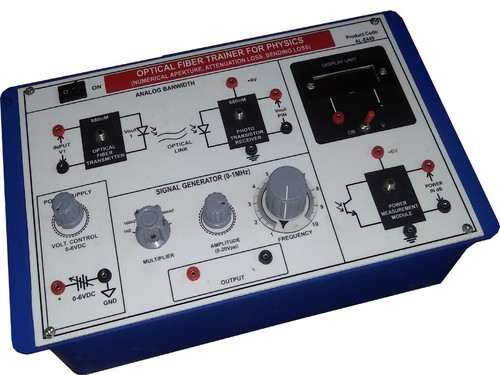
Jump on instant savings with our polished Frequency Response of Optical Receiver at Different Bandwidth units-a lustrous solution for your laboratory testing needs. This meritorious receiver delivers selectable bandwidths from 10 MHz to 200 MHz with impeccable 0.5 dB accuracy. Powered by a high-grade PIN photodiode and integrated amplifier, it ensures a dynamic range over 70 dB and low-noise design (<3 dB). Equipped with BNC output, LED indicators, and RF-shielded enclosure, it's optimized for optical characterization. Limited time offers available-contact us for your distributor in India.
Advanced Application Surface & Competitive Edge
Engineered for laboratory and indoor use, this Optical Receiver Frequency Response Unit is ideal for precise characterization of optical receiver performance at varying bandwidths. Utilized by researchers, technicians, and engineers, its competitive edge lies in its low-noise design, versatile bandwidth selection, and high dynamic range. These features provide outstanding measurement confidence both in academic and industrial settings-making it the trusted choice for demanding test environments.
Reliable Supply Ability & Smooth Transaction Terms
Our supply ability ensures timely dispatching and rapid arrival for bulk and sample orders. Payment terms are flexible, supporting easy exchanges and secure transactions. Samples are available for evaluation before purchase, promoting trust with new customers. As a manufacturer, supplier, exporter, distributor, and trader from India, we prioritize efficient logistics, helping you complete your acquisition process seamlessly for all optical receiver testing requirements.
FAQ's of FREQUENCY RESOPONSE OF OPTICAL RECEIVER AT DIFFERENT BANDWITH:
Q: How does the selectable bandwidth improve frequency response characterization?
A: Selectable bandwidth ranging from 10 MHz to 200 MHz enables precise tuning for various optical receiver specifications, allowing users to tailor measurement conditions to meet diverse application needs and ensure accurate frequency response analysis.
Q: What are the advantages of using a PIN photodiode in this receiver?
A: A PIN photodiode offers high sensitivity and linearity, providing reliable optical-to-electrical conversion, which results in enhanced measurement accuracy and consistent performance across selected bandwidths.
Q: When can I expect the unit to be dispatched after placing an order?
A: Product dispatching typically occurs within 3-5 business days following order confirmation and payment. Shipping timelines may vary depending on quantity ordered and destination.
Q: Where is this optical receiver frequency response unit primarily used?
A: This unit is primarily used in laboratory settings and indoor environments, where controlled conditions are required for advanced optical and RF characterization tasks.
Q: What is the process for requesting a sample before purchase?
A: To request a sample, contact our sales team, specifying your evaluation requirements. Samples are subject to availability, and we ensure swift dispatch and exchange for qualifying customers.
Q: How does the integrated amplifier benefit frequency response measurements?
A: The integrated amplifier boosts signal strength and lowers noise, ensuring greater measurement fidelity and enabling detection of minute frequency variations for robust characterization results.


 Send Inquiry

 English
 Spanish
 French
 German
 Italian
 Chinese (Simplified)
 Japanese
 Korean
 Arabic
 Portuguese